Showing your work is much better than describing it. On this page I’ll show non-proprietary stuff as samples. Just starting out there’s a schematic sample I did for my last job. They requested a Brushless DC Motor Drive of 1kW capability and not having any switching components.
Linear Brushless DC Motor Drive
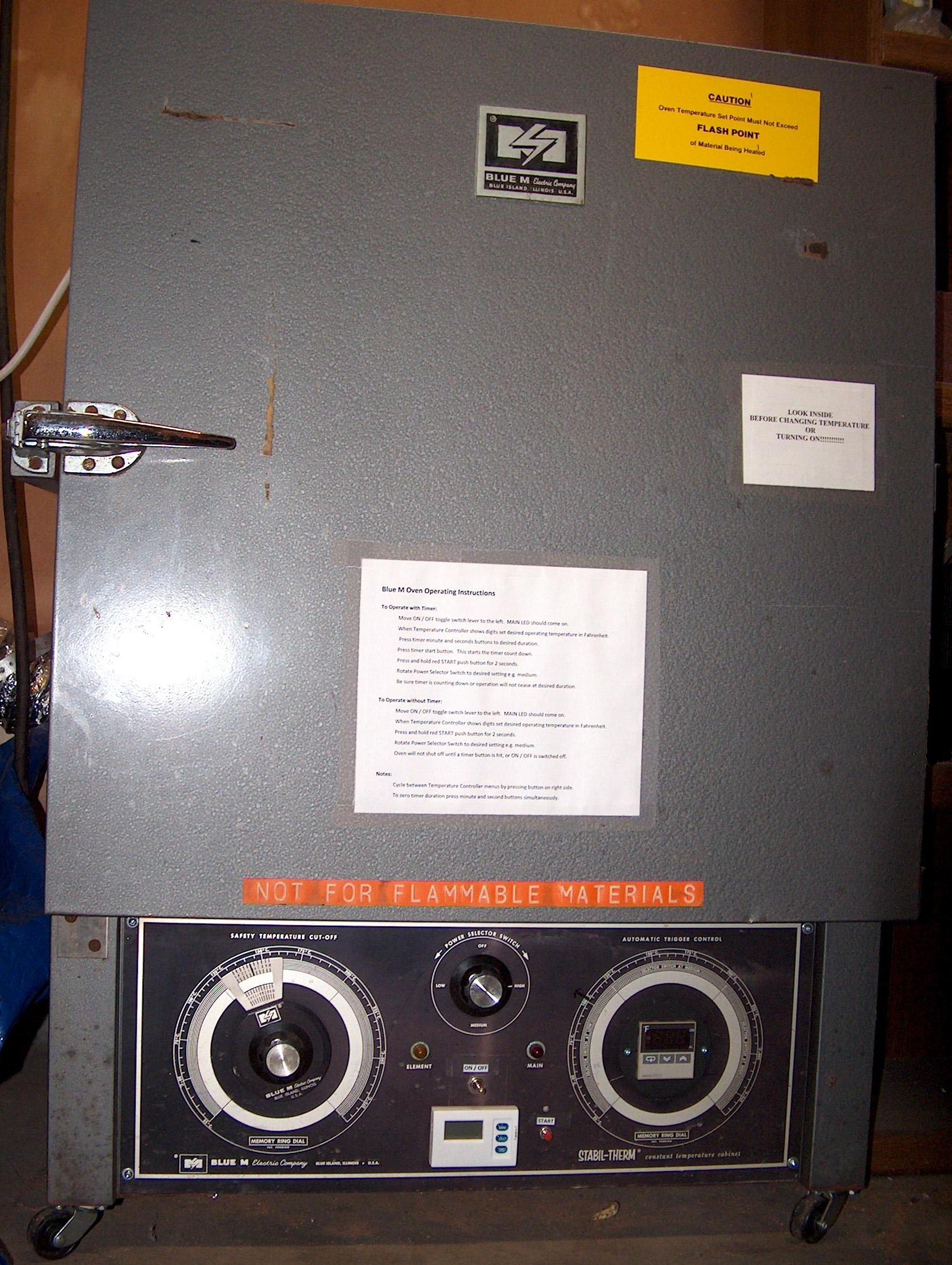
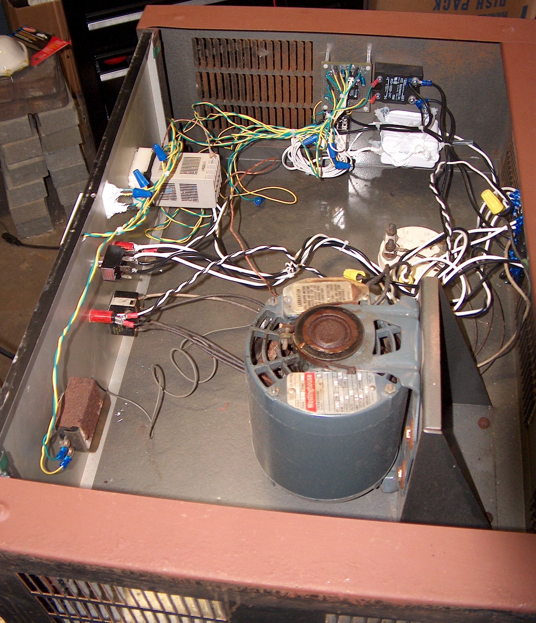
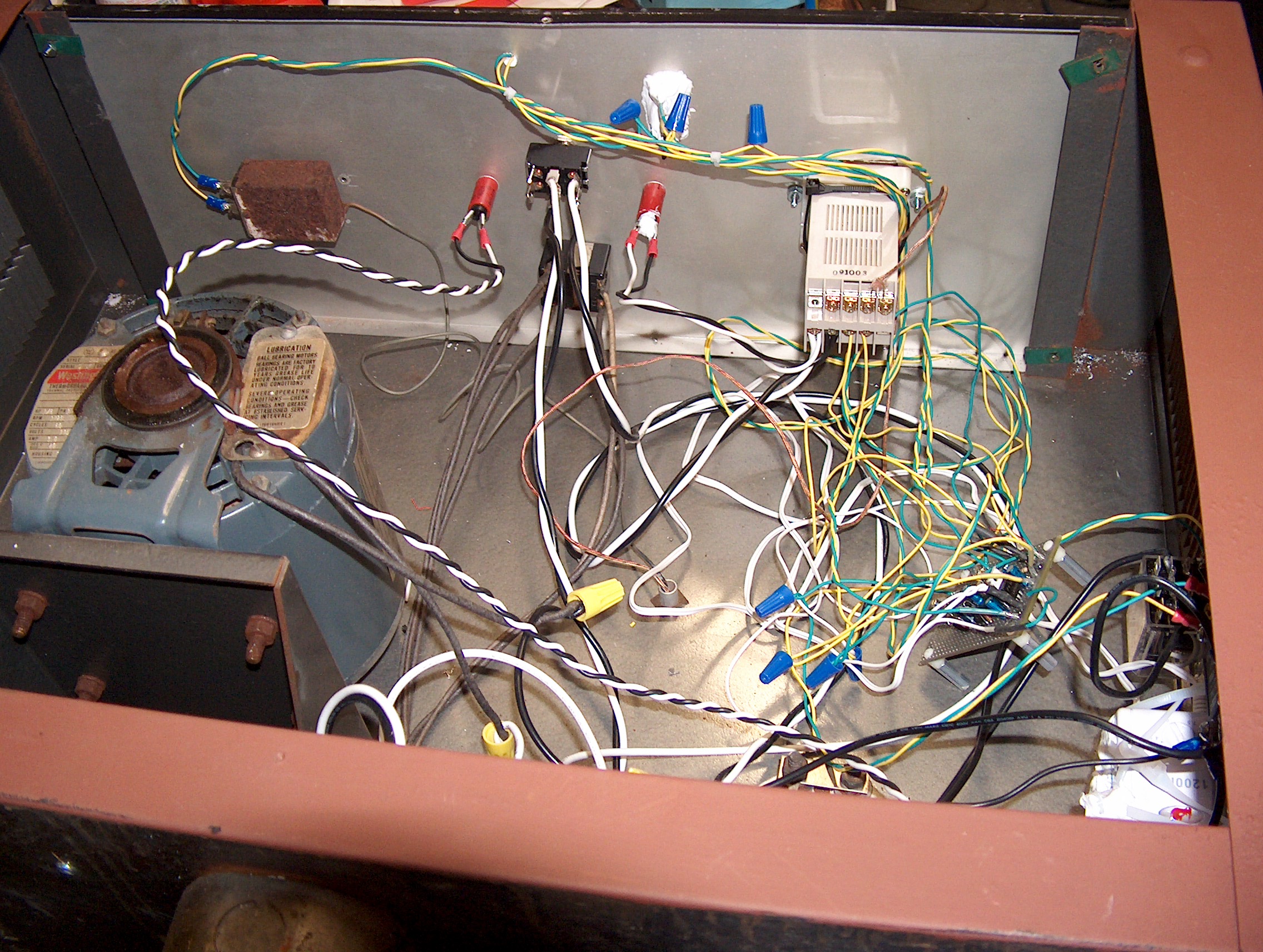
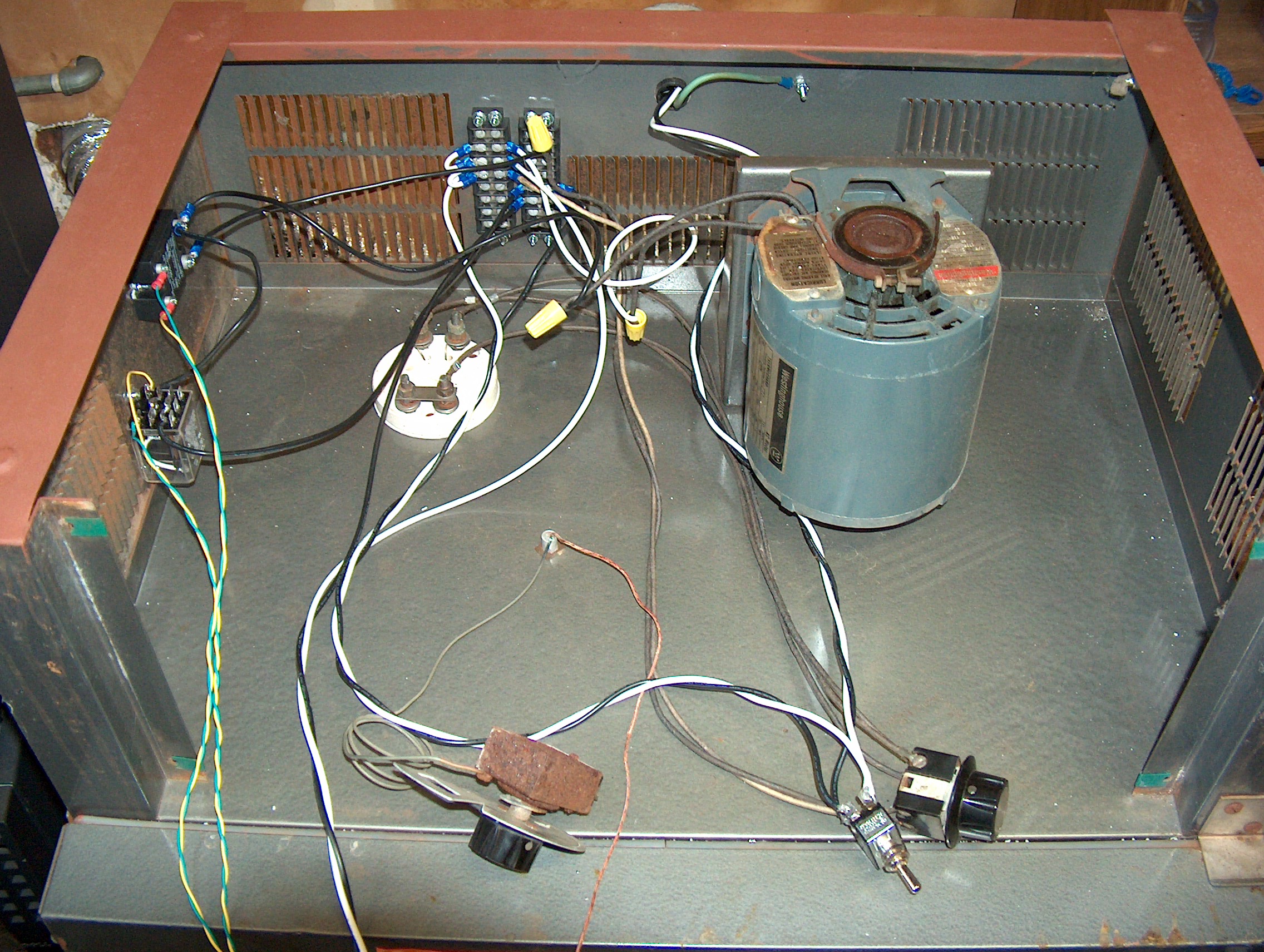
I refurbished an old Blue M Environmental Cabinet adding some Digital controls for my garage workshop. Since a contract position needed me to know “Eagle” schematic capture and PCB layout. I created a document package and a sample PCBA using CadSoft USA’s “Eagle”. Look at some *.pdf's of schematics and PCB layout. Pictures of Blue M Cabinet: Blue M, Front, Blue M, nearly finished, Blue M, proto board, and Blue M, just starting.
Please request a circuit sample if you would like to see my work. Also I would be happy to do circuit simulations having OrCAD complete suite V9.1 (or LTspice), and can send you the sources or *.pdf’s.
Although my recent work is more analog hardware (with some digital), I have done some major test programs. Some descriptions follow.
For software there’s a VB6.0 class final project. I have done some newer stuff, but can’t show it since it is IP belonging to my former company.
Look at a *.pdf of a VB6 final class project.
You’ll have to magnify the printing with acrobat to really read anything here.
Download a copy of the project *.zip
This should be extracted to some temp folder and then the project opened with VB6.0.
The additional code examples shown below are all C. I’ve refreshed my C skills with VC++ 6.0 recently.
If you can imagine a 4’ X 6’ X 6’ Semi Capital Equipment
tool; you might understand the need for a lot of computing power. There are 5 axes of motion, auxiliary
equipment, machine vision, material loading, and communications. But there’s also the actual measurement
equipment to run. For the Stylus
NanoProfilometer it was decided that dual processor boards was necessary. On separate passive backplanes 2 single board
computers were used. A
Look at a *.pdf of the main *.cpp file. Look at the D_P_TST2.cpp file.
Look at a *.pdf of the subroutine *.cpp file. Look at the D_P_SUB1.cpp file.
Look at a *.pdf of a timer driver *.cpp file. Look at the D_TIMER1.cpp file.
Here’s some code that can be viewed with VC++6.0, but you must compile with DJGPP creating a project with the 3 *.cpp files.
Download the *.cpp and *.h files to build the project.
All files needed are in the zip file, but setting up the DJGPP environment is something else.
The PCI End Point Bridge was originally designed by a consultant and the chief engineer. The consultant generated small test programs that contained code to load the timer, exercise mailboxes, and memory from each of the processor board sides. I took over the board set and fixed many hardware bugs and completed the release. Later, I wrote extensive test software for both processor boards. The consultant’s original code is included in my programs as subroutines “host_ramp_test” and “ctrl_ramp_test”. To test the boards the Ctrl1 program is run on the P4, and the Host1 program run on the WINNT processor. Use of a second keyboard and display is preferred, but it was possible to swap keyboard, and SVGA cable between processor boards for the tests requiring entry from both sides.
These files can be viewed with Notepad and so *.pdf files are not needed.
Down load *.c and *.h files for Ctrl1 in *.zip.
Look at the hostmailbox1.c file.
Download *.c and *.h files for Host1 in *.zip.
When I was taking night classes and a lot more interested in Space type issues, I decided to write a simulation program for Ion Acceleration. In summary if using below a few dozen mg of fuel per second and you have immense amounts of power, then just about any point in the solar system is accessible. The travel periods are in months, not years. I have no real idea of the efficiencies of present state of art ion propulsion technology. Also, I assume this simulator is more efficient than an actual real world system. There’s lots of formulas in the program to account for ion interactions and will give your processor quite a workout. It’s on this webpage to serve as a sample of my old C programming and should work fine under WIN XP.
Download the Ion-Acl.cpp and Ion-Acl.exe in *.zip.
I have an early C program that was extra credit for an Advanced C programming class I took. The file has been resurrected and compiled under Borland C++ 5.0. It should work fine under WIN XP.
Look at the Xtrcred1.cpp file.
This should be viewable with Notepad. Use of something like VC++ 6.0 will show the line indenting a lot better than notepad.
Download a copy of the Xtrcred1.exe and the source.
This will compile under Borland C++ 5.0 and not VC++ 6.0 etc.
Send me an email with your request for sample work: ron@ron-selman.com.